Delivering High Quality Stainless Steel and Alloy Piping Products — Pipes, Tubes, Fittings, Flanges and more for Global Industries.
sales@savoypipinginc.comDelivering High Quality Stainless Steel and Alloy Piping Products — Pipes, Tubes, Fittings, Flanges and more for Global Industries.
sales@savoypipinginc.com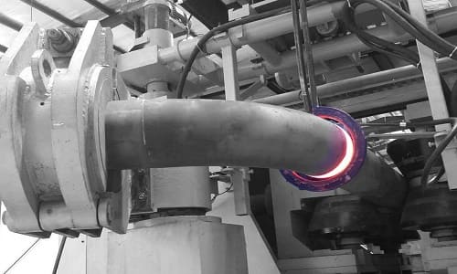
Savoy Piping Inc. offers a diverse range of API 5L Hot Induction Bend Pipes made of Carbon steel. These pipes canter to industries such as Power, Oil and Gas, Construction, and Chemical.
Our Bending Process adheres to EN 1559-1 Standards and Customer Specifications, Ensuring Precise Manufacturing and Narrow Tolerances in Wall Thickness Reduction, Ovality, Bending Radius, and Angles. We can Bend both Seamless and Welded Pipes within a Bending Radius Range of 3D-10D.
The Hot Induction Bending Process Involves Locally Heating the Pipe for Easy Bending. We are pleased to Provide Quotations for induction bent Pipes such as API 5L Grade B, API 5L X42, API 5L X46, API 5L X52, API 5L X56, API 5L X60, API 5L X65 Etc. as well as pipes conforming to European norms. When subjected to Hot Bending (above 750°C), the Mechanical Properties of the Material are Preserved. Additionally, we offer Post-Bending Heat Treatments like Normalizing and Stress Relief Heat Treatment at our Facilities.
During the Final Inspection, we Conduct Dimensional and Visual Controls, Hydro Tests, and 100% Non-Destructive Testing on Welds to Ensure Minimal Tolerances on Bends.
| Hot Induction Bend Pipe Type | Seamless / Welded / ERW / LSAW / SSAW / EFW |
| Hot Induction Bend Pipe Diameter | 4” – 48” |
| Hot Induction Bend Pipe Thickness | Upto 60 mm |
| Hot Induction Bend Bending Radius | 2D – 10D ( Max. R =9754 mm) |
| Hot Induction Bend Bending Angle | 0° – 180° |
| Hot Induction Bend Angle Tolerance | ± 0.5° |
| Hot Induction Bend Radius Tolerance | ≤ 5 mm |
| Hot Induction Bend Ovality At Ends | ± 1% |
| Hot Induction Bend Ovality on Body | 4D & above to 6% |
| Hot Induction Bend Wall Thinning | 4D & above ≤ 8% |
| Hot Induction Bend Approval | RINA, PED-23, ISO 9001, IBR, EIL, OHSAS |
| Hot Induction Bend Manufacturing Standard | ISO 1559-1 Induction Bends – Petroleum and Natural Gas Industries Got Bends, Fittings and Flanges for Pipeline Transportation Systems AS 2885 – Gas and Liquid Petroleum DNV-OS-F101 – Offshore Standard for Submarine Pipeline Systems ASME B31.1 – Power piping ASME B31.3 – Process piping ASME B31.4 – Pipeline Transportation Systems for Liquids and Slurries ASTM A403- ASME SA403 – Standard Specification for Wrought Austenitic Stainless Steel Piping Fittings ASME B16.9 – Factory-Made Wrought Fittings Buttwelding ASME B16.25 – Buttwelding Ends ASME B16.28 – Wrought Steel Short Radius Elbows and Buttwelding Returns MSS SP-43 – Wrought and Fabricanted Butt-Welding Fittings for Low Pressure, Corrosion Resistant Applications ASME B16.49 – Factory-made Carbon Steel Pipe bend |
| Pipe Raw Material for Hot Induction Bends | Carbon Steel Pipes (API 5L Gr.B / ASTM A106 Gr.B / A671 CC60, CC65, CC70 / A672 C60, C65, C70 / IS 3589 FE350, FE410) High Strength Steel Pipes (API 5L X42, X52, X56, X60, X65, X70) in PSL 1 and PSL 2 Low Temperature Alloy Steel (ASTM A333 Gr.6) Alloy Steel Chrome Moly Alloys (ASTM A335 Grade P5, P9, P11, P22, P91 / A691) Stainless Steel Pipes (ASTM A312 304, 304L, 316, 316L, 321 etc) Duplex & Super duplex Steel, including 22% Cr (UNS S31803) & 25% Cr (UNS S32750/60) High Chrome Steel Pipes (ASTM A335, P11, P22, P91) High Nickel High Chrome Steel Pipes (Inconel / Monel / SMO 254 / Hastelloy C22, C276) Cladded Pipes All Pipes as per ASME, ASME, DIN & EN Standards |
| Hot Induction Bend Post-Bending Heat Treatment | Normalizing: This treatment is commonly used for carbon steels like ASTM A106 Gr. B, A333 Gr. 6, and API 5L X52. Normalizing and Tempering: Primarily applied to materials with a higher chromium content, such as ASTM A335 P11 and P22, among others. Quenching and Tempering: This Post-Bending Treatment is suitable for High Yield Materials like API 5L X65. Solution Annealing: This Process can be Applied to Stainless and Duplex Steels, such as 304, 304L, 316L, UNS S31803 and UNS S32760. |
| Hot Induction Bend Testing & Inspection | Mechanical Testing, Universal Testing Machine, Charpy Testing, Hardness Tester, Hydro Testing, Beveling Machine, Thickness Gauge, Non-destructive Testing ( X-ray/UTI/MPI ), Microscope for Metallographic Analysis, Spectrometer for Chemical Analysis, Corrosion Testing, Hydrogen-induced Cracking (HIC), Sulfide Stress Corrosion Cracking (SSCC) |
| Hot Induction Bend Coating | Fusion Bonded Epoxy Coating(FBE Coating), 3LPE Coating (Three Layer Polyethylene), 3LPP Coating (Three Layer Polypropylene), Any Poweder & Liquid Epoxy Coating, Internal & External Coating, Food Grade Epoxy Coatings, Anti-rust painting |
Induction Bending offers Numerous Advantages that make it a Preferred choice for Pipe Nending Applications. Firstly, it ensures Improved Quality with Precise Dimensional Controls and accuracy in terms of Radius, Angle, Ovality, and Wall thinning. The process results in uniform Hardness and a Better Surface Finish, Eliminating Pipe Wrinkles.
In addition, Induction Bending Provides Processing Flexibility and can be applied to a wide range of Materials such as Carbon steel, Alloy steel, and Stainless steel. It allows for the Production of Multiple bends and enables the Creation of Precise customized Pipe bends, Saving both Time and Effort. Unlike other bending methods, Induction Bending does not require Sand Filling or Insertion of Inner mandrels, Significantly Reducing Bending Time.
Another Significan't Advantage is the Integrity it maintains in the Pipe Work. Induction bends are piggable, meaning they allow for Easy Passage of cleaning devices through the Pipeline, Reducing the need for welding in many Applications. Moreover, the large Radius of Induction Bends Enhances Fluid Flow, Promoting Efficient Operation and Minimizing Friction, wear, and Pump Energy Consumption.
From a Cost Perspective, Induction Bending proves to be Cost-efficient as it Eliminates the need for standard components like Elbows, Reducing costs Associated with Materials. It also replaces Elbows with Larger Radius Bends where appropriate, resulting in Reduced friction, Wear, and pump energy consumption. By Decreasing the number of welds, particularly at Critical points, induction Bending Enhances Pressure and Stress Absorption, thus reducing the need for Costly Non-Destructive testing like X-ray Examination of Welds.
Furthermore, induction bending reduces the inventory of Elbows and standard bends, making it easier to maintain a Smaller Stock. Straight Pipes, which are Readily Available, can be bent Faster and at Lower Costs Compared to Elbows or Standard Components. The process also requires Minimal Tool requirements, Eliminating the need for Thorns or Mandrels used in Cold Bending.
Lastly, Induction Bending is a Clean process that does not require Lubricantion, and the water used for cooling can be recycled, contributing to a more environmentally friendly operation. Overall, the various advantages of Induction Bending make it a preferred choice for Industries seeking Improved Quality, Cost Efficiency, and enhanced Fluid flow in their Piping Systems.
| Steel Grade | Mass fraction, % based on heat and product analyses a,g | ||||||
|---|---|---|---|---|---|---|---|
| C | Mn | P | S | V | Nb | Ti | |
| max b | max b | max | max | max | max | max | |
| Seamless Pipe | |||||||
| A | 0.22 | 0.9 | 0.3 | 0.3 | – | – | – |
| B | 0.28 | 1.2 | 0.3 | 0.3 | c,d | c,d | d |
| X42 | 0.28 | 1.3 | 0.3 | 0.3 | d | d | d |
| X46 | 0.28 | 1.4 | 0.3 | 0.3 | d | d | d |
| X52 | 0.28 | 1.4 | 0.3 | 0.3 | d | d | d |
| X56 | 0.28 | 1.4 | 0.3 | 0.3 | d | d | d |
| X60 | 0.28 e | 1.40 e | 0.3 | 0.3 | f | f | f |
| X65 | 0.28 e | 1.40 e | 0.3 | 0.3 | f | f | f |
| X70 | 0.28 e | 1.40 e | 0.3 | 0.3 | f | f | f |
| Welded Pipe | |||||||
| A | 0.22 | 0.9 | 0.3 | 0.3 | – | – | – |
| B | 0.26 | 1.2 | 0.3 | 0.3 | c,d | c,d | d |
| X42 | 0.26 | 1.3 | 0.3 | 0.3 | d | d | d |
| X46 | 0.26 | 1.4 | 0.3 | 0.3 | d | d | d |
| X52 | 0.26 | 1.4 | 0.3 | 0.3 | d | d | d |
| X56 | 0.26 | 1.4 | 0.3 | 0.3 | d | d | d |
| X60 | 0.26 e | 1.40 e | 0.3 | 0.3 | f | f | f |
| X65 | 0.26 e | 1.4 e | 0.3 | 0.3 | f | f | f |
| X70 | 0.26e | 1.65 e | 0.3 | 0.3 | f | f | f |
| a. Cu ≤ = 0.50% Ni; ≤ 0.50%; Cr ≤ 0.50%; and Mo ≤ 0.15%, b. For each reduction of 0.01% below the specified maximum concentration for carbon, an increase of 0.05% above the specified maximum concentration for Mn is permissible, up to a maximum of 1.65% for grades ≥ L24 or B, but ≤ L360 or X52; up to a maximum of 1.75% for grades > L360 or X52, but < L485 or X70; and up to a maximum of 2.00% for grade L485 or X70., c. Unless otherwise agreed NB + V ≤ 0.06%, d. Nb + V + TI ≤ 0.15%, e. Unless otherwise agreed., f. Unless otherwise agreed, NB + V = Ti ≤ 0.15%, g. No deliberate addition of B is permitted and the residual B ≤ 0.001% |
|||||||
| Steel Grade | Mass fraction, % based on heat and product analyses | Carbon Equiv a | |||||||||||||||||||
|---|---|---|---|---|---|---|---|---|---|---|---|---|---|---|---|---|---|---|---|---|---|
| C | Si | Mn | P | S | V | Nb | Ti | Other | CE IIW | CE Pcm | |||||||||||
| max b | max | max b | max | max | max | max | max | max | max | ||||||||||||
| Seamless and Welded Pipe | |||||||||||||||||||||
| BR | 0.24 | 0.4 | 1.2 | 0.025 | 0.015 | c | c | 0.04 | e,l | 0.43 | 0.25 | ||||||||||
| X42R | 0.24 | 0.4 | 1.2 | 0.025 | 0.015 | 0.06 | 0.05 | 0.04 | e,l | 0.43 | 0.25 | ||||||||||
| BN | 0.24 | 0.4 | 1.2 | 0.025 | 0.015 | c | c | 0.04 | e,l | 0.43 | 0.25 | ||||||||||
| X42N | 0.24 | 0.4 | 1.2 | 0.025 | 0.015 | 0.06 | 0.05 | 0.04 | e,l | 0.43 | 0.25 | ||||||||||
| X46N | 0.24 | 0.4 | 1.4 | 0.025 | 0.015 | 0.07 | 0.05 | 0.04 | d,e,l | 0.43 | 0.25 | ||||||||||
| X52N | 0.24 | 0.4 | 1.4 | 0.025 | 0.015 | 0.1 | 0.05 | 0.04 | d,e,l | 0.43 | 0.25 | ||||||||||
| X56N | 0.24 | 0.4 | 1.4 | 0.025 | 0.015 | 0.10f | 0.05 | 0.04 | d,e,l | 0.43 | 0.25 | ||||||||||
| X60N | 0.24f | 0.4f | 1.40f | 0.025 | 0.015 | 0.10f | 0.05f | 0.04f | g,h,l | As agreed | |||||||||||
| BQ | 0.18 | 0.4 | 1.4 | 0.025 | 0.015 | 0.05 | 0.05 | 0.04 | e,l | 0.43 | 0.25 | ||||||||||
| X42Q | 0.18 | 0.4 | 1.4 | 0.025 | 0.015 | 0.05 | 0.05 | 0.04 | e,l | 0.43 | 0.25 | ||||||||||
| X46Q | 0.18 | 0.4 | 1.4 | 0.025 | 0.015 | 0.05 | 0.05 | 0.04 | e,l | 0.43 | 0.25 | ||||||||||
| X52Q | 0.18 | 0.4 | 1.5 | 0.025 | 0.015 | 0.05 | 0.05 | 0.04 | e,l | 0.43 | 0.25 | ||||||||||
| X56Q | 0.18 | 0.4f | 1.5 | 0.025 | 0.015 | 0.07 | 0.05 | 0.04 | e,l | 0.43 | 0.25 | ||||||||||
| X60Q | 0.18f | 0.4f | 1.70f | 0.025 | 0.015 | g | g | g | h,l | 0.43 | 0.25 | ||||||||||
| X65Q | 0.18f | 0.4f | 1.70f | 0.025 | 0.015 | g | g | g | h,l | 0.43 | 0.25 | ||||||||||
| X70Q | 0.18f | 0.4f | 1.80f | 0.025 | 0.015 | g | g | g | h,l | 0.43 | 0.25 | ||||||||||
| X80Q | 0.18f | 0.4f | 1.9f | 0.025 | 0.015 | g | g | g | i,j | As agreed | |||||||||||
| X9Q | 0.16f | 0.4f | 1.9 | 0.02 | 0.01 | g | g | g | j,k | As agreed | |||||||||||
| X100Q | 0.16f | 0.4f | 1.9 | 0.02 | 0.01 | g | g | g | j,k | As agreed | |||||||||||
| Welded Pipe | |||||||||||||||||||||
| BM | 0.22 | 0.4 | 1.2 | 0.025 | 0.015 | 0.05 | 0.05 | 0.04 | e,l | 0.43 | 0.25 | ||||||||||
| X42M | 0.22 | 0.4 | 1.3 | 0.025 | 0.015 | 0.05 | 0.05 | 0.04 | e,l | 0.43 | 0.25 | ||||||||||
| X46M | 0.22 | 0.4 | 1.3 | 0.025 | 0.015 | 0.05 | 0.05 | 0.04 | e,l | 0.43 | 0.25 | ||||||||||
| X52M | 0.22 | 0.4 | 1.4 | 0.025 | 0.015 | d | d | d | e,l | 0.43 | 0.25 | ||||||||||
| X56M | 0.22 | 0.4f | 1.4 | 0.025 | 0.015 | d | d | d | e,l | 0.43 | 0.25 | ||||||||||
| X60M | 0.12f | 0.4f | 1.60f | 0.025 | 0.015 | g | g | g | h,l | 0.43 | 0.25 | ||||||||||
| X65M | 0.12f | 0.4f | 1.60f | 0.025 | 0.015 | g | g | g | h,l | 0.43 | 0.25 | ||||||||||
| X70M | 0.12f | 0.4f | 1.70f | 0.025 | 0.015 | g | g | g | h,l | 0.43 | 0.25 | ||||||||||
| X80M | 0.12f | 0.4f | 1.85f | 0.025 | 0.015 | g | g | g | i,j | .043f | 0.25 | ||||||||||
| X9M | 0.1 | 0.55f | 2.10f | 0.02 | 0.01 | g | g | g | i,j | – | 0.25 | ||||||||||
| X100M | 0.1 | 0.55f | 2.10f | 0.02 | 0.01 | g | g | g | i,j | – | 0.25 | ||||||||||
| a. SMLS t>0.787”, CE limits shall be as agreed. The CEIIW limits applied fi C > 0.12% and the CEPcm limits apply if C ≤ 0.12%, b. For each reduction of 0.01% below the specified maximum for C, an increase of 0.05% above the specified maximum for Mn is permissible, up to a maximum of 1.65% for grades ≥ L24 or B, but ≤ L360 or X52; up to a maximum of 1.75% for grades > L360 or X52, but < L485 or X70; up to a maximum of 2.00% for grades ≥ L485 or X70, but ≤ L555 or X80; and up to a maximum of 2.20% for grades > L555 or X80., c. Unless otherwise agreed Nb = V ≤ 0.06%, d. Nb = V = Ti ≤ 0.15%, e. Unless otherwise agreed, Cu ≤ 0.50%; Ni ≤ 0.30% Cr ≤ 0.30% and Mo ≤ 0.15%, f. Unless otherwise agreed, g. Unless otherwise agreed, Nb + V + Ti ≤ 0.15%, h. Unless otherwise agreed, Cu ≤ 0.50% Ni ≤ 0.50% Cr ≤ 0.50% and MO ≤ 0.50%, i. Unless otherwise agreed, Cu ≤ 0.50% Ni ≤ 1.00% Cr ≤ 0.50% and MO ≤ 0.50%, j. B ≤ 0.004%, k. Unless otherwise agreed, Cu ≤ 0.50% Ni ≤ 1.00% Cr ≤ 0.55% and MO ≤ 0.80%, l. For all PSL 2 pipe grades except those grades with footnotes j noted, the following applies. Unless otherwise agreed no intentional addition of B is permitted and residual B ≤ 0.001%. |
|||||||||||||||||||||
| Pipe Grade | Tensile Properties – Pipe Body of SMLS and Welded Pipes PSL 1 | Seam of Welded Pipe | ||
|---|---|---|---|---|
| Yield Strength a | Tensile Strength a | Elongation | Tensile Strength b | |
| Rt0,5 PSI Min | Rm PSI Min | (in 2in Af % min) | Rm PSI Min | |
| A | 30,500 | 48,600 | c | 48,600 |
| B | 35,500 | 60,200 | c | 60,200 |
| X42 | 42,100 | 60,200 | c | 60,200 |
| X46 | 46,400 | 63,100 | c | 63,100 |
| X52 | 52,200 | 66,700 | c | 66,700 |
| X56 | 56,600 | 71,100 | c | 71,100 |
| X60 | 60,200 | 75,400 | c | 75,400 |
| X65 | 65,300 | 77,500 | c | 77,500 |
| X70 | 70,300 | 82,700 | c | 82,700 |
| a. For intermediate grade, the difference between the specified minimum tensile strength and the specified minimum yield for the pipe body shall be as given for the next higher grade. | ||||
| b. For the intermediate grades, the specified minimum tensile strength for the weld seam shall be the same as determined for the body using foot note a. | ||||
| Where C is 1 940 for calculation using Si units and 625 000 for calculation using USC units | ||||
| Axc is the applicable tensile test piece cross-sectional area, expressed in square millimeters (square inches) , as follows | ||||
| – For circular cross-section test pieces, 130mm2 (0.20 in2) for 12.7 mm (0.500 in) and 8.9 mm (.350 in) diameter test pieces; and 65 mm2 (0.10 in2) for 6.4 mm (0.250in) diameter test pieces. | ||||
| – For full-section test pieces, the lesser of a) 485 mm2 (0.75 in2) and b) the cross-sectional area of the test piece, derived using the specified outside diameter and the specified wall thickness of the pipe, rounded to the nearest 10 mm2 (0.10in2) | ||||
| – For strip test pieces, the lesser of a) 485 mm2 (0.75 in2) and b) the cross-sectional area of the test piece, derived using the specified width of the test piece and the specified wall thickness of the pipe, rounded to the nearest 10 mm2 (0.10in2) | ||||
| U is the specified minimum tensile strength, expressed in megapascals (pounds per square inch) | ||||
| Pipe Grade | Tensile Properties – Pipe Body of SMLS and Welded Pipes PSL 2 | Seam of Welded Pipe | |||||
|---|---|---|---|---|---|---|---|
| Yield Strength a | Tensile Strength a | Ratio a,c | Elongation | Tensile Strength d | |||
| Rt0,5 PSI Min | Rm PSI Min | R10,5IRm | (in 2in) | Rm (psi) | |||
| Af % | |||||||
| Minimum | Maximum | Minimum | Maximum | Maximum | Minimum | Minimum | |
| BR, BN,BQ,BM | 35,500 | 65,300 | 60,200 | 95,000 | 0.93 | f | 60,200 |
| X42,X42R,X2Q,X42M | 42,100 | 71,800 | 60,200 | 95,000 | 0.93 | f | 60,200 |
| X46N,X46Q,X46M | 46,400 | 76,100 | 63,100 | 95,000 | 0.93 | f | 63,100 |
| X52N,X52Q,X52M | 52,200 | 76,90 | 66,700 | 110,200 | 0.93 | f | 66,700 |
| X56N,X56Q,X56M | 56,600 | 79,000 | 71,100 | 110,200 | 0.93 | f | 71,100 |
| X60N,X60Q,S60M | 60,200 | 81,90 | 75,400 | 110,200 | 0.93 | f | 75,400 |
| X65Q,X65M | 65,300 | 87,000 | 77,600 | 110,200 | 0.93 | f | 76,600 |
| X70Q,X65M | 70,300 | 92,100 | 82,700 | 110,200 | 0.93 | f | 82,700 |
| X80Q,X80M | 80,.500 | 102,300 | 9,600 | 119,700 | 0.93 | f | 9,600 |
| a. For intermediate grade, refer to the full API5L specification. | |||||||
| b. for grades > X9 refer to the full API5L specification. | |||||||
| c. This limit applies for pies with D> 12.750 in | |||||||
| d. For intermediate grades, the specified minimum tensile strength for the weld seam shall be the same value as was determined for the pipe body using foot a. | |||||||
| e. for pipe requiring longitudinal testing, the maximum yield strength shall be ≤ 71,800 psi | |||||||
| Where C is 1 940 for calculation using Si units and 625 000 for calculation using USC units | |||||||
| Axc is the applicable tensile test piece cross-sectional area, expressed in square millimeters (square inches) , as follows | |||||||
| – For circular cross-section test pieces, 130mm2 (0.20 in2) for 12.7 mm (0.500 in) and 8.9 mm (.350 in) diameter test pieces; and 65 mm2 (0.10 in2) for 6.4 mm (0.250in) diameter test pieces. | |||||||
| – For full-section test pieces, the lesser of a) 485 mm2 (0.75 in2) and b) the cross-sectional area of the test piece, derived using the specified outside diameter and the specified wall thickness of the pipe, rounded to the nearest 10 mm2 (0.10in2) | |||||||
| – For strip test pieces, the lesser of a) 485 mm2 (0.75 in2) and b) the cross-sectional area of the test piece, derived using the specified width of the test piece and the specified wall thickness of the pipe, rounded to the nearest 10 mm2 (0.10in2) | |||||||
| U is the specified minimum tensile strength, expressed in megapascals (pounds per square inch | |||||||
| g. Lower values fo R10,5IRm may be specified by agreement | |||||||
| h. for grades > x9 refer to the full API5L specification. | |||||||
We canter to Diverse Industries, including Oil and Gas, where Hot Induction Bends find Extensive Applications. Our Hot Bending Solutions meet Stringent Specifications and Industry Standards, Making them Ideal for High-Temperature Pipe Bending in Demanding Environments - Oil and Gas Equipments, Offshore Technology, Seawater Desalination Plants, Chemical Industry, Bridges, Storage Tanks, Medical Industry, Civil Engineering, Pressure Vessels, Reactor Tanks, and Heat Exchangers, Rotors, Impellers and Shafts, Power Plants, Petrochemical, Shipbuilding Industry, Pumping Stations, Nuclear Power.
We Export API 5L Hot Induction Bends to Saudi Arabia, Iran, Iraq, United Arab Emirates, Qatar, Bahrain, Oman, Kuwait, Turkey, Egypt, Yemen, Syria, Israel, Jordan, Cyprus, Singapore, Malaysia, Indonesia, Thailand, Vietnam, South Korea, Japan, Sri Lanka, Maldives, Bangladesh, Myanmar, Taiwan, Cambodia, Argentina, Bolivia, Brazil, Chile, Venezuela, Colombia, Ecuador, Guyana, Paraguay, Uruguay, United States of America, Canada, Mexico, Panama, Costa Rica, Puerto Rico, Trinidad And Tobago, Jamaica, Bahamas, Denmark, Russia, Norway, Germany, France, Italy, United Kingdom, Spain, Ukraine, Netherlands, Belgium, Greece, Czech Republic, Portugal, Hungary, Albania, Austria, Switzerland, Slovakia, Finland, Ireland, Croatia, Slovenia, Malta, Nigeria, Algeria, Angola, South Africa, Libya, Egypt, Sudan, Equatorial Guinea, The Republic Of Congo, Gabon, Europe, Africa, Asia, North America, South America, Middle East, Far East.etc
Savoy Piping Inc., is a Trusted Induction Bend Suppliers, we Prioritize Customer Satisfaction and Ensure On-Time Delivery of Superior Hot Induction Bending Solutions. Our Expertise in Hot Bending Techniques Combined with a Wide Range of High-Quality Materials Allows us to Provide Tailored Solutions for your Unique Requirements.
hot bend vs cold bend, hot bending process, hot induction bend calculation, hot induction bend manufacturer, hot induction bend manufacturer in uae, Hot induction bends formula, Hot induction bends pdf, induction bend wall thinning calculation, induction bending machine, Induction bends in pipe, Induction bends pdf, Metal pipe bending, Precision pipe bending, Induction bending technology, Heat-induced pipe bends, Induction bending services, Hot bending Applications, Induction bend manufacturers, Induction bending advantages, Hot induction bending specifications, Hot bending for oil and gas industry, High-temperature pipe bending,Hot bending techniques, Induction bending equipment, Induction bend suppliers, Hot induction bending solutions, Heat-formed pipe bends, Induction bending for construction industry, induction bending vs cold bending